

 فارسی
فارسی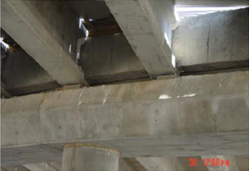
EARTHQUAKE EFFECTS ASSESSMENT ON VULNERABILITY OF EXISTING BRIDGES
M. JAVIDNIA1 , M. S. RAZZAGHI2
1 Master of Science, Islamic Azad University, Qazvin Branch, Iran
2Assistant Professor, Islamic Azad University, Qazvin Branch, Iran
ABSTRACT
Earthquake is one of the most important factors which causes damage to bridges. There are several existing pre-seismic code bridges. In such bridges no seismic code considered in design and construction of the structure. We should have specific consideration for retrofitting activities, especially in area of high level seismicity, in order to reduce seismic risks in these lifelines.
In this research the damages of bridges in recent earthquakes have been studied, and the main reasons for vulnerability of bridges and also the techniques of retrofitting the existing or under construction bridges are discussed.
Keywords: Bridge, lifelines, retrofitting, earthquake, isolator, seismic vulnerability.
1. INTRODUCTION
One of the important measures for growth and development in each country is construction of roads and highways. Bridges as key elements in the transportation network of a country provide unique and important economic, social and political roles. Based on the important role of the bridges after an earthquake, it is necessary for these structures to have higher level of seismic protection. Damage to bridges due to past seismic events, clearly expressed the necessity of earthquake resistant design strategies and further research in order to better understanding the seismic behavior of the bridges (Basoz 1999).
Recent seismic events all over the world have shown that bridge structures are particularly sensitive to earthquake loading. There are several reasons for such sensitivity. First many existing bridges were designed without adequate consideration for seismic risk. This has resulted to inadequate detailing of confining steel and insufficient shear reinforcement in the bridge piers, insufficient seat length of bearings, and inadequate strength and stiffness of the superstructure-abutment connection. Furthermore, there are many open questions concerning the ductile behavior of large bridge piers, in particular those with rectangular hollow cross-section. Also, the seismic zone map of many European countries has been revised recently, prescribing now higher horizontal ground accelerations in several regions. Finally, local soil conditions and the possibility of asynchronous motion at the base of the piers of long bridges are factors which can cause additional difficulties in properly designing irregular bridges. (Park 1987)
During the past decades large earthquakes in US, Japan, Taiwan and Turkey caused several impacts to the bridges. This paper summarizes the major failure modes of the bridges and causes of these failure modes. Furthermore typical strategies for seismic retrofit of vulnerable bridges are summarized.
2. MAJOR FAILURE MODES OF BRIDGES
Damage to bridges may occur due to the several reasons such as material, hydrological, geotechnical and structural failure. Improper design, poor construction, Excessive loading design, the executive weakness, excessive stress and displacement of foundation can cause damage to bridges (Tahoni 2011).
A plenty of common failure modes of the bridges are presented below:
2.1. Damage to shear key and bent caps
Shear keys, are secondary components that prevent decks from lateral movement. Lack of attention to these can be adverse impact on performance of bridge. Following the Chi-Chi (Taiwan) earthquake of 1999, Yen-Feng bridge was damaged because of poor design of shear keys. As indicated in Figure 1 damage to shear keys caused movement of the deck and lead to residual relative displacement of the deck (Hsu and Fu 2004).
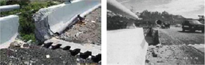
Figure 1: Creating residual cross-displacement due to failure of shear keys of Yen-Feng bridge (Hsu and Fu 2004).
2.2. Shear failures of bridge piers
According to seismic design codes, it is necessary to use special stirrups in order to create sufficient ductility and prevent shear failure of bridge piers. Furthermore sufficient anchorage length of longitudinal reinforcement should be considered. Figure (2) illustrates the sudden shear failure for reinforced concrete columns of bridge with insufficient brace lengths in 1995 Kobe earthquake in Japan (Kawashima and Hasegawa 1994).
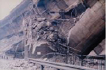
Figure 2: Sudden shear failure of reinforced concrete bridge columns (Kawashima and Hasegawa 1994).
2.3. Girder failures and span collapse:
Decks and girders of bridges have usually sufficient strength, so damage to decks and girders are consequences of failure of other members. Insufficient seat width along with rotation of piers, are two major reasons for seismic damage of decks (Pamuk et al. 2005).
2.4. Excessive deformation of slabs
This type of failure occurs because of foundation movement or settlement of abutments embankments. Figure (3) shows fallen Wu-shi bridge spans because of piers failure and settlement to be caused by displacement (Yen 2002).
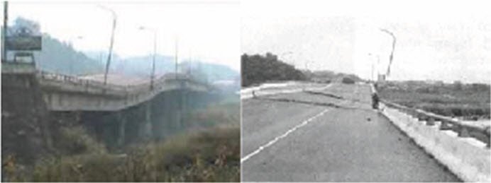
Figure 3: Deformation happened on Wu-shi bridge (Yen 2002).
3. THE MAJOR CAUSES OF BRIDGES FAILURES DURING THE EARTHQUAKE
Philosophy governing on the design of new bridges and retrofitting the existing bridge is same, and both are based on functional design. Identifying weakness points in bridges against earthquakes is particularly important in the formulation of instruction and strategy of new bridge design and retrofitting of existing bridge. The main causes of bridges failure during an earthquake can be expressed as follows:
3.1. Damage due to faulting and liquefaction
By displacement of the fault caused by the earthquake, the piers are involved in crack and rotation, girders are skidding upon the bent caps and spans collapse. Sometimes, despite the observation of regulation conditions, bridge spans will collapse because of 5 to 6 meters vertical displacement arising from fault displacement across the bridge location (Pamuk et al. 2005).
3.2. Cut off in the continuity of spiral reinforcement at plinth of bridge, in zone of plastic joints configuration
Considering the earthquake energy damping, regulations allow that some predetermined zones in the structures suffer plastic deformation with keeping the hardness, strength and ductility in the reciprocal cycles of earthquake waves. These zones are usually selected under the piers for bridges. Created discontinuity will cause reduction of enclosure stresses in plinth and will be a very important factor in considerable reduction of ductility, and instability of bridge piers in earthquake.
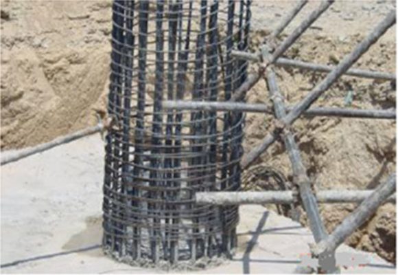
Figure 4: Spiral reinforcement has cut off in plinth at time foundation construction (Saadatmehr 2006).
3.3. Longitudinal reinforcement splice at plinth of bridge, in zone of plastic joints configuration
Based on the points have been referenced in the previous section and according to the provisions of the regulations, the column longitudinal reinforcement splice is only permitted in the middle zone of column height. The minimum length of splice is 60 times of longitudinal reinforcement diameter and special spiral conditions should be observed. In figure (5) unfortunately reinforcement splice is exactly placed in column unauthorized zone and spiral reinforcement has been cut off in foundation.

Figure 5: Placed reinforcement splice in column unauthorized zone (Saadatmehr 2006).
3.4. Lack of supplying the necessary length for bent caps of precast reinforced concrete beams of bridge deck
In the bridges consist of deck with precast reinforced concrete beams, using of Neoprene elastomeric support is very common for seat of beams in the place of abutment and piers. During the earthquake, the bridge longitudinal displacement due to the lack of damping in this type of seat is significant. Therefore, the regulations are provided that the length of deck seat on the bridge piers and abutments should have a minimum rate due to prevent the fall of the deck upon the piers and abutments into spans (fig.6).
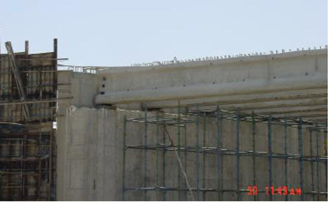
Figure 6: Lack of supplying the length of deck seat in order to prevent the fall of the deck (Saadatmehr 2006).
3.5. Incorrect locating of Neoprene below the precast beams of bridge deck
According to the provisions of regulations, tetrahedral neoprene axis, should be coincide on axis of the beam and the sides are parallel to the sides of the beam, because of prevent the non-uniform pressure outside of the axis. Figure (7) illustrates that both of the above cases has not been considered, and neoprene have been installed with a significant eccentricity, and this matter leads to the reduction of useful life of neoprene operation and creation considerable stresses at the end of beam.
Figure 7: Installation neoprene with significant eccentricity (Saadatmehr 2006).
3.6. Poor curing of the deck concrete and creation of shrinkage cracks
Sometimes contractors take wet gunny sack for curing deck slab concrete instead of using plastic nylon. Whereas the wind rising or existence of open pores on the surface of gunny sack, moisture quickly evaporates and several cracks occur on the surface of the slab. These cracks (see fig.8) will cause to penetration of corrosive materials to the coat of the slab reinforcement with few cover and consequently the corrosion of reinforcement, concrete failure around it and reduction of useful operation life of bridge will occur.
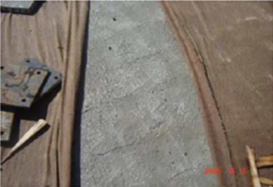
Figure 8: Creation of several surface cracks on the the slab (Saadatmehr 2006).
3.7. The inappropriate implementation of expansion joints
Implementation of the expansion joints is usually coincident with slab concreting. At this time because of low precision in execution of expansion joints, and the lack of lining asphalt, the surface of the joint and concrete around it will have ripples, and will not be modified during implementation of asphalt. Therefore, the area of expansion joints should not be concreted until the bridge asphalt execution (Saadatmehr 2006).
4. RETROFITTING AND SEISMIC REHABILITION OF BRIDGES
Considerable damages in the bridge piers are classified into two groups: 1- Dependent on the pier flexural failure due to insufficient flexural strength and with insufficient flexural ductility capacity, 2- Dependent on the pier shear failure of bridge due to insufficient shear capacity. The main purpose of seismic rehabilitation of reinforced concrete columns is shear strength increasing, especially in piers with longitudinal reinforcement cutting in the middle of height without sufficient anchorage length. This will increase the ductility of the column by preventing premature shear failure. If only the ductility increases, the residual deformation in piers may be increased after the earthquake. Also the pier flexural strength should be increased, which leads to an increase in the transitional earthquake load from piers to foundation (Aboutaha et al. 1999).
The procedures for repairing and retrofitting in most countries include methods such as improvement of soil condition, or increasing area of supports by increasing number of piles where the foundation has damaged. Method such as replacement of materials, adding steel and concrete jacket are used when materials are destructed (Department of Education, Research and Technology 2006).
5. THE NEW METHODS OF BRIDGES RETROFITTING
Methods of bridges retrofitting which were common in the past, but nowadays are less considered, include piers retrofitting with steel jacket, using Λ brace on both sides of the column, bridge concrete columns retrofitting with pedestal, using steel shear head in concrete blocks. Today, the use of the isolator, dampers, integrated systems, retrofitting with FRP and etc. could be the next alternative. Using the isolator and energy damper systems in the bridges makes the focus of damage caused by the earthquake in the location of supports systems, so piers and abutments are protected against structural damage (Vetr and Garmehi 2006).
5.1. Isolators
Isolators are used in order to isolate the structure against intensive earth motion during earthquakes. Despite the building that is often isolated above foundation, in bridges this separation is applied between superstructure and substructure (see fig.9). Large inertial forces of superstructure (including the weight of the deck) and ease of execution is cause of this fact. Generally, these isolators are used in two cases of rubber and friction in bridges.
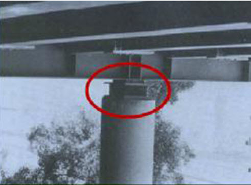
Figure 9: The location of the seismic isolation in the column head (Maleki 2006).
5.2. Dampers
The resulting displacement, due to the effect of applied dynamic loads, will have speed and acceleration. The effect of dynamic damage and side transfer of structure can be minimized by installing damper (Maleki 2006).
5.3. Retrofitting with FRP
The FRP wraps are mainly used for rehabilitation of existence structures behavior or repairing damages which created in existence structures due to fatigue, corrosion and etc. In this method decks are made from concrete and FRP composite, and concrete is poured into the FRP panels, and deck is connected to beams with shear reinforcements. After putting panels on the steel beam, shear reinforcements are welded. Concrete haunch will be put between the composite deck panels and steel beams (Ringelstetter et al. 2006).
6. CONCLUSION
According to the type of failures, the following results can be noted:
1- Plastic joints are not formed in the deck and non-linear analysis should be used to determine their location.
2- Shear keys and sufficient bent cap width should be provided for protecting the bridge from unexpected impacts that might be created by effect of earth damage or liquefaction.
3- Shear failure in piers should be avoided. For this purpose, spiral and sufficient stirrups should be used in piers, and reinforcement should not be cut in middle of piers height.
4- In places that the possibility of soil liquefaction is so much, its effect should be considered in design.
7. REFERENCE
Aboutaha RS, Engelhardt MD,Jirsa JO, and Kreger NE (1999). Rehabilitation of Shear Critical Concrete Columns By Use of Rectangular Steel Jackets. Journal of ACI Structural. 96(1). pp. 68-78.
Bason NI (1999). Statistical analysis of bridge damage data from 1994 Northridge, CA, earthquake. Journal of Earthquake Spectra. 15 (1), pp. 25-54.
Department of Education, Research and Technology, Department of Comparative Studies (2006). Regulations of repair and retrofit of bridges sub structural. Organization for Economic Cooperation and Development (OECD) Inc. pp. 123-127.
Hsu YT and Fu CC (2004). Seismic Effect on Highway Bridges in Chi-Chi Earthquake”, Journal of Performance of Constructed Facilities. 18(1). pp . 43-47.
Kawashima K and Hasegawa K (1994). New seismic design specifications of highway bridges in Japan. Journal of Earthquake Spectra. 10(2), pp. 333-356.
Maleki SH (2006). New methods of bridges retrofitting . Proceedings Firth Congress on Introduction with New Technologies of Seismic Rehabilitation, Tehran, pp. 215-231.
Park Y.J (1985). Mechanistic Seismic Damage Model for Reinforced Concrete. Journal of Structure Enggineering. 111(4), pp.504-524.
Pamuke A, Kalkan E, and Ling HI(2005). Structural and geotechnical impact of surface rupture on highway structure during recent earthquakes in Turkey. Journal of Elsevier, soil Dynamics and earthquake Engineering. 25(1). pp. 581-589.
Ringelstetter T.E, Bank L.C, Matta F, and Nanni A (2006). Development of a cost-Effective Structural FRP Stay-In-Place Formwork System for Accelerate and Durable Bridge Deck Construction. Journal of Official Magazine of the American Composites Manufacturers Association. 17(3), pp.183-189.
Saadatmehr I (2006). some points about execution of reinforced concrete bridge. Journal of Structure and Computer. 3(13), pp. 33-40.
Tahoni SH (2011). Design of Bridges. Tehran University Inc. Ninth Edition.
Vetr M.gh, and Garmehi V(2006). Seismic retrofit of highway bridges reinforced concrete columns based on shaking table. Proceedings Firth International Congress on Seismic Retrofitting, Tehran, pp. 943-954.
Yen WH (2002). Lessons learned about bridges from earthquake in Taiwan. Journal of Federal Highway Administration. 65(4). pp. 52-68.